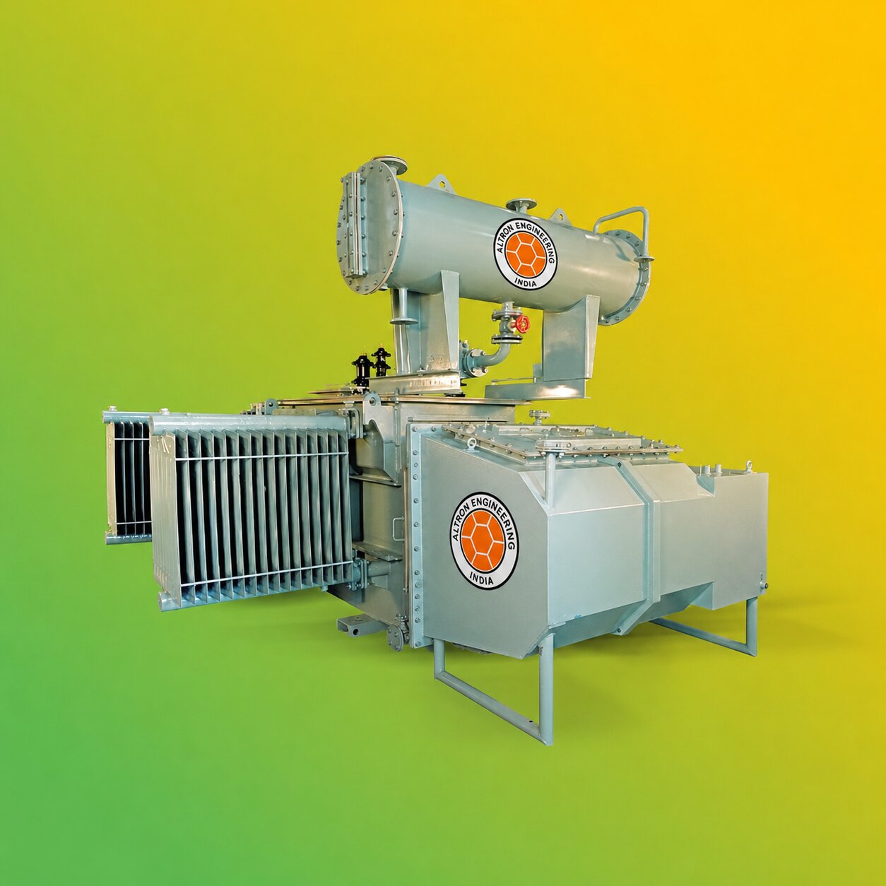
Power transformers are among the most crucial components of modern power systems. It is used to transfer power from one circuit the next while reducing or increasing the voltage based on the needs of the system. But what is the process by which an electric power transformer works? The answer lies in the concept of electromagnetic induction. A transformer utilises an electric field created by alternating currents to transfer electricity between secondary and primary windings, without altering the frequency of the electricity.
Power transformers are extensively used in power ; renewableelectricity. generation facilities as well as transmission substations and industrial installations Renewable energy initiatives, as well as large electrical distribution systems.In this tutorial we will go over the power transformer's working principles, the main components, its voltage transformation process, the various types and typical applications.
What Is a Power Transformer?
Power transformers are static electrical devices which transfer AC electrical energy to the two circuits or even more by electromagnetic induction. Its main function is to alter the voltage while preserving an equal frequency. Based on the arrangement of the winding, it is possible to boost or decrease voltage.
For instance:
- The step-up transformer can increase the voltage.
- The step-down transformer reduces the voltage.
- An isolation transformer transmits power while maintaining roughly the same power-to-voltage ratio.
Power transformers are especially important in high-voltage electrical systems because they permit electricity to be efficiently transmitted across long distances.
How Does a Power Transformer Work?
The fundamental principle of operation of a power transformer is founded on Faraday's law of electromagnetic induction. .
When an alternating voltage is transferred to the winding that is primary, an alternating current is pushed through it. This causes a change in magnetic flux inside its magnetic centre.
The fluctuating magnetic flux flows across the second winding and creates the electromotive force (EMF) within the winding.
The voltage generated in the secondary winding is determined by the proportion of turns that are split between the primary and secondary windings. .
In a simple perfect transformer, the relation between winding turns and voltage is understood through the ratio of turns. This lets engineers develop transformers that meet the necessary voltage for a specific electrical system.
Step-by-Step Working of a Power Transformer
Understanding the procedure step-by-step will make it easier to comprehend the way the power transformer functions.
1. AC Voltage Is Applied to the Primary Winding
The process starts by supplying an alternating electric current applied to the main winding of the transformer.
The primary winding consists of conductive insulation about the magnet core. .
2. Current Produces a Magnetic Field
The alternating current that flows across the main winding produces an ever-changing magnetic field.
The transformer's core is an extremely low-reluctance pathway for this magnetic flux, which allows it to connect effectively with the secondary winding. .
3. Magnetic Flux Passes Through the Core
The transformer core is typically made of magnetic steel that has been laminated or other magnetic materials that are suitable.
The flux of magnetic energy changes through the core and connects both the secondary and primary windings.
4. Voltage Is Induced in the Secondary Winding
In the case of electromagnetic induction, the fluctuating magnetic flux causes an increase in voltage in the secondary winding.
The magnitude of inducing voltage is largely determined by how many turns are on the secondary winding compared to those of the main winding.
5. Voltage Is Increased or Decreased
The transformer alters the voltage based on its turn ratio.
In the event that the second winding is equipped with greater turns than its primary counterpart, then the voltage of the output rises.
In the event that the secondary winding is made up of fewer turns, the voltage output drops.
This simple concept lets transformers adapt the electrical voltage to various levels of power generation distribution, transmission and industrial usage.
Understanding the Transformer Turns Ratio
The ratio of turns is one of the most crucial concepts to understand the way the power transformer functions.
In a perfect transformer it is linked to the turns ratio
V2/V1 = N2/N1
Where:
- V1 = Primary voltage
- V2 = Secondary voltage
- N1 = The number of primary winding turns
- N₂ = the number of secondary winding turn
For instance, if the secondary winding has twice the number of turns as the primary winding, the secondary voltage would be about twice that of the primary voltage in ideal conditions.
In the real world, operational factors and losses can cause performance to differ little from the ideal ratio.
Main Components of a Power Transformer
A power transformer consists of several elements which work in tandem to offer an efficient and safe voltage transformation.
1. Magnetic Core
The core is a conduit for magnetic flux between windings.
It is usually made of electrical steel laminated to decrease eddy-current losses.
2. Primary Winding
The primary winding is able to receive electric energy from the input source.
The number of turns can be chosen based on the required voltage and the transformer's design.
3. Secondary Winding
The secondary winding provides the electrical energy transformed to the plugged load as well as to the electrical circuit.
The number of turns it has determines the voltage output relative to the winding that is primary.
4. Insulation System
Insulation helps separate the conductive parts and prevents electrical breakdown.
In accordance with the construction of the transformer, the insulation materials could include pressboard, paper, varnish resin, oil and various other special materials.
5. Transformer Oil
Oil-immersed power transformers make use of insulation oil to provide cooling and electrical insulation.
The oil assists in transferring warmth away from the core and windings towards the cooling system.
6. Bushings
Bushings offer insulated connections between internal transformer windings as well as external electrical conductors.
7. Cooling System
Power transformers generate heat during operation. Cooling systems aid in keeping the transformer's operating temperature.
The design of the transformer as well as the rating of it, cooling may be accomplished by forced air or insulating oil circulation or any other method.
Why Does a Power Transformer Need a Core?
Magnetic cores are crucial for the efficient transfer of energy from the main and secondary winds.
If there was no proper magnetic path, a large part of the magnetic flux would not be able to effectively connect with the second winding.
A properly designed core
- Offers a highly efficient magnetic route
- Improves magnetic coupling
- Helps reduce losses
- Supports efficient voltage transformation
- Contributes to the overall performance of transformers
The core is typically laminated to limit unwanted circulating currents referred to as eddy currents.
Step-Up vs Step-Down Power Transformer
Power transformers are designed to either increase or reduce the voltage.
| Feature | Step-Up Transformer | Step-Down Transformer |
|---|---|---|
| Principal Purpose | Increases the voltage | Decreases the voltage |
| Secondary Turns | More than the primary | Fewer than the primary |
| Common Application | Power transmission | Industrial and distribution systems |
| Current | Decreases as voltage increases, ideally | Increases as voltage decreases, ideally |
| Typical Location | Near generating stations | Substations and electrical infrastructure |
Both systems operate on the same basic concept that is the electromagnetic principle.
Why Are Power Transformers Used in Electricity Transmission?
The electricity generated by power plants must travel for a long distance before it can reach industrial facilities and consumers. The transmission of electricity at higher voltage permits the same amount of power to be delivered at a lower current. A lower current reduces resistive distortions in conductors for transmission. This is the reason an average power system might utilise the following:
Generation - Step-Up Transformer - High-Voltage Transmission - Step-Down Transformer - Distribution - End User
Power transformers thus form an essential link between the various voltage levels in the electric grid.
Applications of Power Transformers
Power transformers are employed in numerous industries where electricity needs to be transferred or the voltage levels must be altered.
Power Generation Plants
Transformers boost the voltage generated by power plants prior to the time electricity is transmitted to the transmission network.
They are utilised in:
- Thermal power plants
- Hydroelectric power plants
- Solar power plants
- Wind power projects
- Other generators that are not utility-scale
Transmission Substations
High-voltage transformers are utilised at substations for varying the voltage as electricity flows throughout the distribution network.
Industrial Facilities
Industries that have large electrical loads need to be able to rely on voltage transformation in order to operate large electrical and mechanical equipment as well as heavy machinery.
Power transformers are utilised in a variety of industries, including:
- Steel
- Cement
- Manufacturing
- Chemicals
- Metals
- Infrastructure
- Process industries
Renewable Energy Projects
Wind and solar power plants require transformers in order to capture and transfer electricity generated at a suitable voltage.
The special transformers, like solar-duty transformers, are utilised for the installation of renewable power sources.
Large Commercial Facilities
Large structures and infrastructure facilities could require transformers to be an element of the electrical distribution system.
What Causes Losses in a Power Transformer?
While transformers are extremely effective electrical appliances, real transformers have some energy loss.
The most common types are:
Copper Losses
Copper losses happen because the windings exhibit electrical resistance. The flow of current through the windings creates heat.
Core Losses
The most common core losses are:
- Losses in Hysteresis
- Eddy-current losses
These losses are caused by the magnetic core when there is the process of alternating magnetisation.
Stray Losses
The loss of stray energy can be caused by magnetic fields that leak out and interact with the conductive structural elements.
Dielectric Losses
Insulating materials may also suffer minor electrical losses, notably at higher voltages.
Transformer design is designed to reduce the losses while ensuring the reliability, thermal performance and cost efficiency.
How Is a Power Transformer Cooled?
It is produced by the transformer windings and in the magnetic core in the course of the process. A proper cooling system is essential to ensure high operating temperatures.
Based on the design of the transformer It could involve:
- Natural air cooling
- Forced air cooling
- Natural oil circulation
- Oil circulation by force
- Radiators
- Fans
- Pumps
Power transformers that are oil-immersed typically use radiators as well as other cooling arrangements to help disperse heat.
The right cooling system is based on the transformer's capacity and design conditions for installation, as well as the operating specifications.
Importance of Power Transformer Maintenance
Knowing the way the power transformer functions is only one part of ensuring its operation is reliable. Regular inspection and maintenance are equally important.
The type of transformer used will determine the maintenance programme. The maintenance programme may comprise the following:
- Examining the condition of transformer oil
- Checking the condition of bushings
- Monitoring the temperature
- Confirming connections
- Inspecting cooling equipment
- Testing insulation
- The monitoring of unusual noises or vibrations
- Monitoring protection and control systems
Regular maintenance will help you detect any issues that may be developing and lower the possibility of sudden failures and downtime.
How to Choose the Right Power Transformer
The right transformer must be chosen based on the operating and electrical needs for the particular project.
The most important considerations are the following:
- Rated capacity of power
- Output voltage and input voltage
- Frequency
- Characteristics of the load
- Transformer type
- Method of cooling
- Installation environment
- The requirements for insulation
- Efficiency
- Capacity to withstand short-circuits
- Standards applicable to the situation
- Maintenance needs
In the case of large utility or industrial projects, the choice of transformers must be done using precise specifications for the technical aspects and load specifications.
Conclusion
What, how does a power transformer function? A power transformer uses the electromagnetic force to move electric energy between circuits and then alters the voltage depending on the demands in the system of electricity. The primary winding is able to receive AC electrical energy that causes a change in magnetic flux inside the core. The flux is linked to the secondary winding and creates an increase in voltage. The ratio of turns between windings determines if the transformer raises or reduces the voltage. Due to this principle of operation, power transformers are essential for power generation, distribution, transmission, industrial facilities, and the development of renewable energies. To ensure reliable performance It is essential to choose an appropriate transformer to match the project's power, voltage, capacity in terms of cooling, insulation, and environmental demands. To learn more about transformer solutions and electrical equipment, visit Altron Limited at https://www.altronlimited.com/.

